

Simulation setup
Coordinate system
A profile’s cross-section lies in the x-y plane, in nm. The origin (x = 0, y = 0) is at the horizontal center of the simulation window’s south (bottom) boundary. x runs from -window_width/2 to window_width/2, with east at +x, and y runs from 0 to window_height, with north up. A shape’s position is its center in these coordinates and defaults to (0, ‘auto’). An ‘auto’ y stacks the layer on top of the previous one, and the first such layer is the substrate, which rests on y = 0 and continues downward without bound.
A port’s window and a section’s offset are placed by their origin, the horizontal center and bottom edge of the window, displaced by offset = (dx, dy) from the section’s own origin. Connecting two ports makes their origins coincide (see connect_ports).
Sections are laid out along the EME propagation axis z. The first section declared starts at the origin and defines the global frame, and each connection places the next section where its port meets the one before. Along a section, w is the distance along its own path and x is across it in the section’s own frame, so after a bend the section’s x turns with it. plot(view='layout') draws the z-x panel in these chip coordinates, both in μm, with x increasing downward.
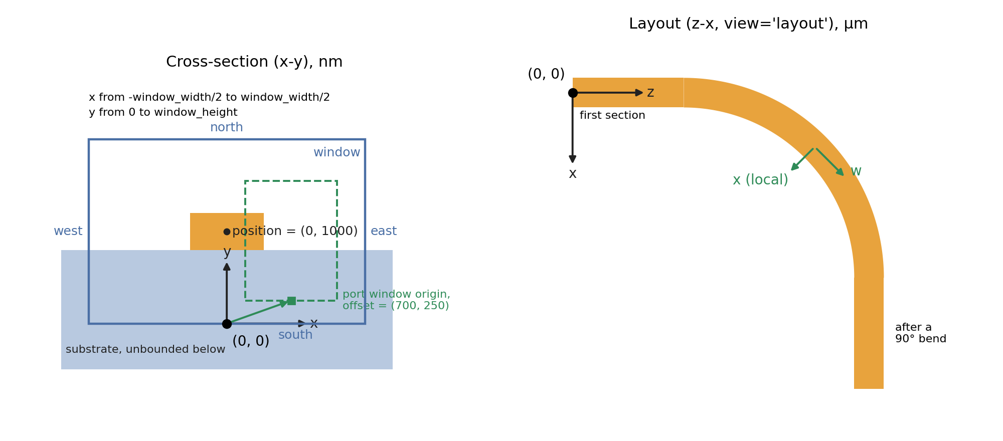
Left, a cross-section: the window, a shape at position = (0, 1000) on an automatically stacked substrate, and a port window whose origin is offset by (700, 250). Right, a straight section and a 90° bend on the chip, as plot(view='layout') draws them.
- settings
Specify the simulation settings.
- Parameters:
profile (str) – name of the profile these settings apply to, default: ‘_default’
wavelength (float) – [nm] simulation wavelength, or a list of wavelengths for a multi-wavelength profile that
FDM(),FEM(),solve()andEME()solve at each one. Setting a new wavelength on a multi-wavelength profile starts it over at that wavelength, default: 1550frequency (float) – [Hz] simulation frequency (an alternative to setting the wavelength), default: None
excitation (Source or PulsedSource or None) – declare a CW pump driving the circuit (EMode3D only), as
Source(port=..., wavelength=..., mode=0, power=1.0, phase=0.0)fromemodeconnection, wherepoweris in W andphasein radians.portis a bare side (‘left’/’right’) or a qualified ‘<section>.<port>’ name, resolved when the circuit is built, andwavelength[nm] is matched against the circuit’s own wavelengths. This is what makesEMEsolve the power-dependent response of a \(\chi^{(2)}\) section in addition to the small-signal scattering matrix. The result is read back withget('response'), and the declared source withget('sources'). APulsedSourceinstead launches a femtosecond pulse for the pulsed nonlinear solver, see pulsed nonlinear propagation. Default: Nonex_resolution (float) – [nm] resolution in the x-direction, default: 10
y_resolution (float) – [nm] resolution in the y-direction, default: 10
window_width (float) – [nm] simulation window width
window_height (float) – [nm] simulation window height
boundary_condition (str, length = 2) – the boundary condition as two characters ‘XX’, the first for the south wall and the second for the west wall (see the coordinate system). ‘0’ is a metal wall with no symmetry, ‘S’ a symmetry wall where Ex is symmetric and ‘A’ one where it is anti-symmetric. ‘TE’ and ‘TM’ fold the window about every middle the structure is mirror symmetric about, to find the TE and TM modes. ‘TE-h’ and ‘TM-h’ fold only about the vertical middle (x = 0, left-right symmetry), ‘TE-v’ and ‘TM-v’ only about the horizontal middle (y =
window_height/ 2, top-bottom symmetry). Symmetry is a property of the whole cross-section, the material at every point of the window: two cores mirrored about the middle fold, and a shape made of the background material (a SiO2 BOX in a SiO2 background) does not break a fold. A fold the structure does not allow is not applied: ‘TE-h’, ‘TE-v’, ‘TM-h’ and ‘TM-v’ warn and solve the full window, and ‘TE’ and ‘TM’ warn when the structure has no symmetry at all. An explicit ‘S’ or ‘A’ wall is always applied, with a warning when the structure is not symmetric about it, since the solve is then of the mirrored half. In an EME, a fold applies only when every section of the device is symmetric about it (seeEME). With an (anti-)symmetric wall, thepml_NSEW_boolsetting is copied from the north/east perimeter to the south/west perimeter, default: ‘00’num_modes (int) – number of modes to solve for, default: 1
field_to_solve (str) – either ‘Et’ or ‘Ht’ to specify whether the transverse electric field or magnetic field is solved, default: ‘Et’
max_effective_index (float) – maximum value for the effective refractive index, if
max_effective_indexis 0 the maximum refractive index found in the simulation window is used, default: 0tolerance (float) – eigenmode solver convergence tolerance, if
tolerance= 0 the computer’s precision is used, default: 1e-12solver_threads (int) – maximum number of threads the sparse solver uses to factor this profile’s systems, where 0 lets the solver choose (up to every core), default: 0
sparse_solver (str) – sparse direct solver for this profile’s solves, one of
'auto','rslab'or'pardiso', where'auto'uses MKL PARDISO on the x86 installers (Linux, Windows and Intel Mac) and rslab on the Apple silicon installer, and'pardiso'is available only in the x86 installers, default: ‘auto’solver (str) – the mode solver used by
solve(),EME()andsweep(): ‘FDM’ (finite difference), ‘FEM’ (finite element, EMode3D only), or ‘default’, which is the FDM in every session (the FEM runs only when asked for). CallingFDM()orFEM()sets this to that solver, default: ‘default’fem_order (int) – (FEM) element order, 1 or 2. Order 2 converges much faster for the same mesh, default: 2
fem_points_per_wavelength (float) – (FEM) mesh points per wavelength in each material before refinement, default: 4
fem_min_angle (float) – [degrees] (FEM) smallest triangle angle allowed in the mesh, at most 34, default: 30
fem_refine_fraction (float) – (FEM) fraction of the estimated error that each refinement step targets, marking the fewest triangles that carry it, default: 0.5
fem_max_refinements (int) – (FEM) most adaptive refinement steps after the first solve, 0 disables refinement, default: 2
fem_neff_tolerance (float) – (FEM) refinement stops once no requested mode’s effective index changes by more than this relative amount, default: 1e-6
fem_max_dofs (int) – (FEM) refinement stops before a mesh would exceed this many unknowns, default: 2000000
fem_mesh_wavelength (float) – [nm] (FEM) build and refine the mesh at this wavelength and solve every wavelength on it, so the results of a wavelength scan change smoothly with wavelength. 0 meshes each solve at its own wavelength.
sweep()over wavelength, a wavelength list and a pulsed simulation set it to their shortest wavelength when it is 0, default: 0bend_radius (float) – [nm] waveguide bend radius relative to the center of the window, must be positive and larger than window_width/2, if
bend_radius= 0 no bending is used in the calculation, default: 0bend_method (str) – how a nonzero
bend_radiusis solved, either ‘cylindrical’ (the bend factor 1 + x/R added to the mode solver) or ‘TO’ (the straight cross-section solved with its material transformed by the bend’s conformal map, transformation optics). Both work with the FDM and the FEM, in 2D and 3D sessions, and their effective indices differ by about 6e-4 at R = 10 um. With a PML, setmax_effective_indexjust above the guided mode, since a TO bend’s spectrum starts with PML modes.report()names the method next to the solver, and the ‘Bend Mode Solvers’ example compares the two, default: ‘cylindrical’pml_NSEW_bool (list, length = 4) – indicates whether to use a pml on each of the 4 boundaries, [north, south, east, west], 0: no pml, 1: use pml, default: [0,0,0,0]
num_pml_layers (int or list with length = 4) – number of pml layers to use, either a single value that is applied to all boundaries or a list of 4 values, [north, south, east, west]. The FDM’s pml is this many grid cells thick on a boundary whose
pml_thicknessis 0. The FEM has no grid cells, so for the FEM it refines the pml’s mesh instead, and it does not set the pml’s thickness. The default 10 meshes the pml at its material’s resolution, 20 meshes it twice as finely and 5 half as finely. Setting it alone resetspml_thicknessto 0, default: 10pml_thickness (float or list with length = 4) – [nm] pml thickness, either a single value that is applied to all boundaries or a list of 4 values, [north, south, east, west]. This is the delivered thickness, the real extent of the pml’s stretched coordinate from the simulation window edge out to the outer pml wall, so it stays fixed when the resolution changes. That is what a grid convergence sweep needs, since
num_pml_layerscounts cells and so shrinks the absorber as the mesh is refined. In the FDM, a value of 0 on a boundary falls back tonum_pml_layersthere, so the two settings can be mixed per boundary. Because the delivered thickness is the integral of thepml_kappa_max/pml_ordergrading over the layer stack, the number of layers it resolves to depends on those two settings. It is also quantized to a whole number of layers, and a request that does not land on one is rounded with a warning stating what was delivered. The FEM delivers exactly the thickness asked for, and on a boundary where it is 0 the FEM chooses a thickness of twice the pml’s imaginary depth \(\ln(1/R) / 2 k_0\), whichpml_reflection(\(R\)) and the wavelength set. With the defaultpml_reflectionthat is 2.87 um at 980 nm and 4.54 um at 1550 nm. An FEM pml thinner than that depth warns, since the pml’s own modes then rise above the cladding index, where they can hide the guided modes. If bothpml_thicknessandnum_pml_layersare given in the samesettings()call,pml_thicknesstakes precedence. Otherwise whichever of the two was set most recently applies, default: 0pml_order (float) – polynomial grading exponent of the pml stretch profile, default: 3
pml_reflection (float) – the target round-trip reflection that the pml is designed for, which sets the maximum pml conductivity. Must be greater than 0 and less than 1, default: 1e-8
pml_kappa_max (float) – the maximum real coordinate stretch, reached at the outer pml face. Both solvers grade the stretch as 1 + (
pml_kappa_max- 1) upml_order across the pml, from u = 0 at its inner face to 1 at its outer face, so for a givenpml_thicknessa larger value makes the pml’s footprint thinner by the factor 1 + (pml_kappa_max- 1) / (pml_order+ 1), 2.5 at the defaults. It must be at least 1, default: 7pml_alpha_max (float) – the complex-frequency-shifted (CFS) pml term, where 0 disables it. Raise it if the solve returns too many artificial pml modes, where
0.1*omega*eps_0is a reasonable starting point that is small enough to barely move the physical modes, default: 0remove_pml_modes_bool (bool) – automatically remove the artificial modes of the pml regions from the mode list, identified as modes carrying less than 75% of their power inside the simulation window, default: False
pml_seed_bool (bool) – seed the pml eigensolve with the fundamental mode of the same structure solved without a pml, so the guided fundamental lands at mode 0 without a hand-tuned
max_effective_index. This costs one extra single-mode solve, default: Falsebackground_material (str or ~MaterialProperties or ~MaterialSpec) – background material, either a material name (from the material database) or a ~MaterialProperties or ~MaterialSpec object, default: “Vacuum”
expansion_resolution (float or list) – [nm] single value or list of 4 values for the stretched grid resolution (ordered [north, south, east, west]). The grid is gradually transitioned from res to
expansion_resolution, default: 20expansion_size (float or list) – [nm] single value or list of 4 values for the approximate stretched distance (ordered [north, south, east, west]), default: 0
subpixel_avg (bool) – whether to use sub-pixel averaging of the permittivity/permeability at shape boundaries for improved accuracy, default: True
generate_chi2 (bool) – whether to generate the second-order nonlinear susceptibility (chi2) tensor for the simulation window, default: False
include_heat (bool) – whether to include heat-related material properties when meshing for FEM heat calculations, default: True
include_scattering (bool) – compute the interfacial scattering loss of every shape with roughness after each solve of this profile, whether the solve comes from
FDM(),FEM(),solve(),EME()orsweep(), the same as callingscattering()after each one.FDM(scattering=True)does this for a single solve. Default: Falsepropagation_resolution – [nm] resolution in the z-direction for plotting EME propagation results, default: wavelength/10
simulation_name (str) – simulation name, default: ‘emode’
- add_material
Add a custom material by specifying a wavelength dependent equation.
- Parameters:
name (str) – material name, this will override the built-in material name if an identical name is used. A variable
user_material_[name]will be createdrefractive_index_equation (str) – refractive index equation to evaluate as a function of the wavelength parameter ‘x’, where imaginary numbers are specified with a preceding ‘j’. Only the following characters are allowed in the equation string: “0123456789 x j . + - ^ * / ( ) [ ]”. A list of three equations can also be specified for non-isotropic materials, like ‘[n_xx, n_yy, n_zz]’. The string must have less than 1000 characters
wavelength_unit (str) – either ‘nm’ or ‘um’ to specify the unit for the wavelength parameter ‘x’, default: ‘um’
wavelength_range (list) – [um] list of the minimum and maximum wavelength recommended for the refractive index equation, default: [0.2, 2.0]
citation (str) – reference displayed in material explorer for the custom material, default: ‘User defined.’
loss (float) – the loss of the material in ‘dB/m’, default: 0.
thermal_conductivity (float) – [W/m·K] thermal conductivity of the material, default: 1e-10
resistivity (float) – [Ohm-nm] resistivity of the material, default: infinity
dn_dT (float) – [K^-1] change in refractive index per change in temperature, relative to 298 K, default: 0
eps_r_dc (float) – [-] relative permittivity at ~1 kHz, default: 1.0
d (list (3x6) or None) – second-order nonlinear susceptibility d-matrix with shape (3, 6). Use None for linear materials, default: None
phi (float) – [rad] rotation of the crystal about z, applied last, default: 0
theta (float) – [rad] rotation of the crystal about y, default: 0
psi (float) – [rad] rotation of the crystal about its own z axis, applied first, default: 0. The three angles turn the crystal by R = Rz(phi) Ry(theta) Rz(psi), the same convention as
MaterialSpecproperty_refs (dict) – citation string per property name (
'd','r','thermal_conductivity','dn_dT','eps_r_dc','resistivity'), default: {}simulation_name (str) – simulation name, default: ‘emode’
- import_database
Import a custom material database by specifying custom materials in a text file.
- Parameters:
filename (str) – name of text file to be imported
simulation_name (str) – simulation name, default: ‘emode’
Here is an example of several custom materials in the database text file to be imported. See the
add_materialfunction for parameter details. Each custom material must contain thenameandrefractive_index_equation, separated by a new line. Comments can be added with ‘#’ or ‘%’. Aname = ...line starts a new record (the spaces around=are optional). A record with norefractive_index_equationraises an error and nothing in the file is imported.wavelength_rangeis always in um regardless ofwavelength_unit, and defaults to[0.2, 2.0]when omitted.citationmay contain an=sign.name = custom_name_1refractive_index_equation = equation_1wavelength_unit = um (optional)wavelength_range = [0.2, 2.0] (optional)citation = reference_1 (optional, default: “User defined by database import.”)# comment about my custom_SiO2 materialname = custom_SiO2refractive_index_equation = (1 + 0.696166/(1 - (0.0684043/x)^2) + 0.4079426/(1 - (0.1162414/x)^2) + 0.8974794/(1 - (9.896161/x)^2))^0.5wavelength_unit = umwavelength_range = [0.21, 6.7]citation = ‘(1) I. H. Malitson, “Interspecimen comparison of the refractive index of fused silica,” J. Opt. Soc. Am. 55, 1205 (1965). (2) C. Z. Tan, “Determination of refractive index of silica glass for infrared wavelengths by IR spectroscopy,” J. Non-Cryst. Solids 223, 158 (1998).’% comment about my custom_name_3 materialname = custom_name_3refractive_index_equation = equation_3wavelength_unit = nm
- shape
Create or update a shape with attributes. These parameters are saved with ‘shape_’+name+’/’ preceding the attribute name. If a name is not given, a number will be allocated as the shape name.
- Parameters:
profile (str) – name of the profile to add the shape to, default: ‘_default’
name (str) – shape name, default: an auto-generated number
material (~MaterialSpec, ~MaterialProperties, or str) – the material for this shape. Takes a string reference to a material in the Material Database, or a ~MaterialSpec or ~MaterialProperties object. default: “Vacuum”
A shape’s relative permeability comes from its material, for example
material=MaterialProperties(n=1.5, mu=2.0), and the permeability of an etched region fromfill_materialin the same way.shape()has no permeability argument of its own, and the olderpermeabilityandfill_permeabilityarguments raise an error that says so.- Parameters:
loss_dB_per_m (float) – [dB/m] material propagation loss, if not set by the
materialparameter, default: 0vertices (list (N,2), list of list (N,2), or int) – list of N vertices that define a closed polygon, or a list of such vertex lists to define multiple disjoint polygons in one shape. If specified the shape is a polygon (
shape_type‘polygon’) defined byvertices(width,height,position,mask,etch,fillare ignored), to disablevertices, setverticesto 0, default: 0width (float) – shape width, if left unspecified the shape is unbounded in x, extending past both sides of the simulation window, default: None
height (float or str) – shape height, or ‘full_height’ for a shape that is unbounded upward, extending past the top of the simulation window. Nothing can be automatically stacked on top of a shape of unbounded height, default: 0
position (list, length = 2) – centered x and y positions relative to the shape width and height, if the y position is left unspecified then it is treated like a layer stacked on top of the previous layer, and the first such layer is the substrate, unbounded downward past the bottom of the simulation window (a shape with an explicit y position never is), if only a single value is provided it is assumed to be the x position and the y position is left unspecified, default: (0, ‘auto’)
mask (float or list) – mask width for etching, centered on x-position set by
positionandmask_offset, or a list of arbitrary length to specify multiple mask regions in combination with a list ofmask_offsetvalues, default:widthmask_offset (float or list) – the x-position offset for the
maskparameter, or a list of arbitrary length to specify multiple mask regions in combination with a list ofmaskvalues, default:0tone (str) – ‘n’/’N’ or ‘p’/’P’ to define the pattern tone as negative or positive for the
maskparameter, default:netch_depth (float) – etch depth for a layer outside the mask region, thickness =
height-etch_depth. The defaultmaskcovers the full width of the layer, so nothing is etched unless a narrowermaskis given, default: 0sidewall_angle (float) – etched sidewall angle in degrees, 0 is perfectly vertical, 90 is the maximum. It is only applied to etched features (
height,mask, and a nonzeroetch_depthmust all be specified for this parameter to have any effect), default: 0fill_material (~MaterialSpec, ~MaterialProperties, or str) – the material for the fill for this shape. Takes the same values as material, as well as “transparent_fill” (the default). “transparent_fill” results in the fill being the background.
correlation_length (float or list) – interfacial roughness correlation length, a single value is applied to all interfaces, a list of 2 applies the first value to all vertical interfaces and the second value to all horizontal interfaces, and a list with one value per edge of the shape’s outline applies each value to its edge, in the order of the outline’s vertices (for a shape defined by
vertices, the order given), default: [0,0]roughness_rms (float or list) – interfacial roughness standard deviation in nm rms, a single value is applied to all interfaces, a list of 2 applies the first value to all vertical interfaces and the second value to all horizontal interfaces, and a list with one value per edge of the shape’s outline applies each value to its edge, in the order of the outline’s vertices (for a shape defined by
vertices, the order given), default: [0,0]shape_type (str) – set shape type as ‘planar’, ‘conformal’ (only uses
name,material,height, andpriority), ‘polygon’ (only usesname,vertices,materialandpriority), or ‘ellipse’ (only usesname,material,width,height,position,sidewall_angle(the angle of the ellipse), andpriority), default: ‘planar’priority (float) – a number that signifies the order in which shapes will be drawn, a higher priority gets drawn over a lower number priority, default: auto-generated integer based on order called
fem_resolution (float) – [nm] approximate resolution to target for triangular meshing used by FEM functions, default: 500
current (float) – [A] current flowing through the cross-section of the shape, which can generate heat, default: 0
voltage (float) – [V] voltage of the shape, None for floating, default: None
heat_only (bool) – specifies a shape that will only be rendered when meshing for a heat calculation, default: False
simulation_name (str) – simulation name, default: ‘emode’
Note
Shapes are positioned in absolute coordinates, independent of the simulation window, so a shape may extend beyond the window and the window can be resized or offset without re-seating the geometry. A layer whose bottom edge rests on y = 0, the reference plane that the automatic stacking starts from, is treated as the substrate: its material continues downward without bound, so a window that extends below y = 0 resolves to that layer rather than to the background material.
- reset
Clear simulation settings, shape definitions, or both, on one profile (the default profile unless
profileis given).'shapes'removes every user-defined shape from the profile (the background remains) and discards its mesh, mode list, and analysis results.'settings'replaces the profile with a new one of the same name at the default settings, which also removes its shapes, and on the default profile also resetspropagation_resolution.'all'does both. Other profiles are not affected. Any otherkindraises an error, as does a profile that does not exist or one member of a multi-wavelength profile ('NAME.WAVELENGTH'), whose members share their shapes.- Parameters:
kind (str) – either ‘shapes’, ‘settings’, or ‘all’ to specify what data is cleared, default: ‘shapes’
profile (str) – name of the profile to reset, default: ‘_default’
simulation_name (str) – simulation name, default: ‘emode’