

Circuit views
A circuit is more than its S-matrix. Where each section sits on the chip, how the sections are wired, and what the field does inside each one are three different questions, and plot() answers each with its own view. All three work on a circuit with branches or loops, and all three can be zoomed to one section and walked from section to section.
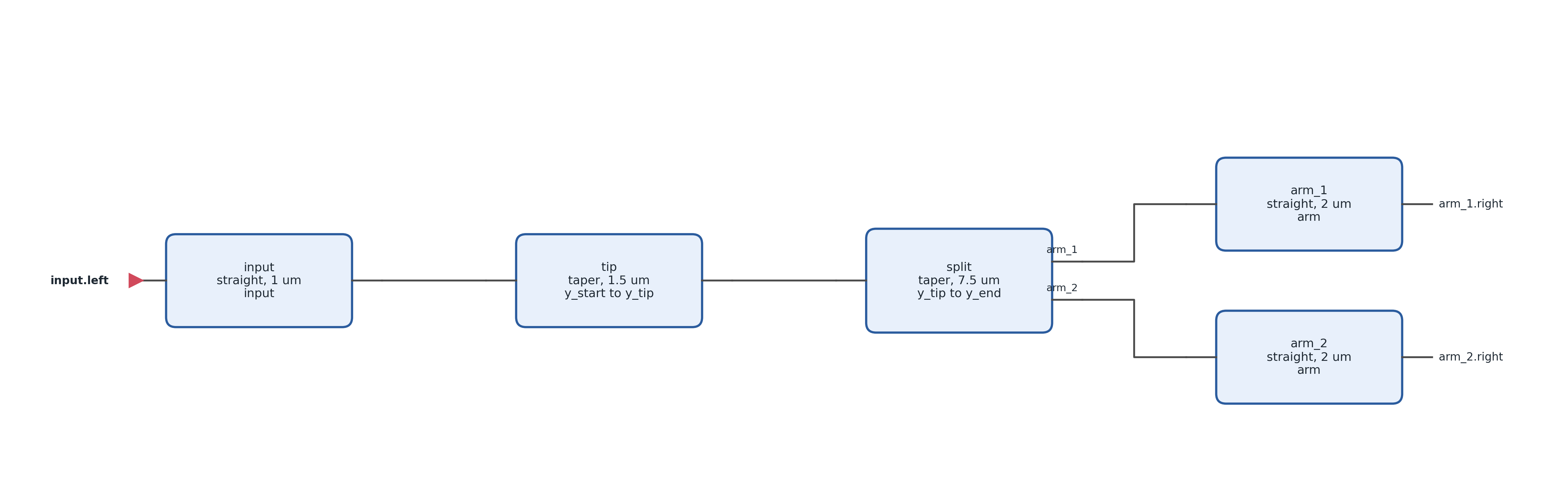
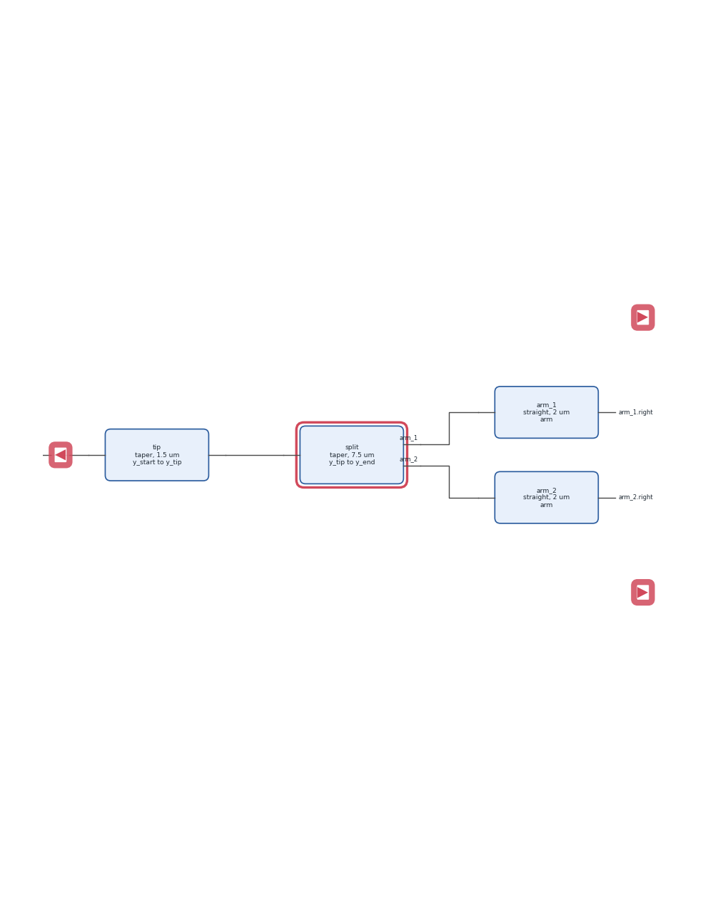
The figures on this page are a Y-branch: an input guide, a tip, a splitter that carries two output windows, and two output guides. The first two sections are input and tip, the splitter is split, and the outputs are arm_1 and arm_2. The ports are wired with connect_ports. The full-size circuit, with its results, is the EME: Y-Branch example.
The three views
Schematic. plot(view='schematic') draws the circuit as a block diagram. Blocks run left to right along the light path, and the arms of a branch are stacked with the lower arm (the one with the lower y) drawn lower. Each block names its section, its kind, its length and its profile or profiles. Ports are stubs on the side they sit on and carry the names they were declared with, connections are lines, and a connection that closes a loop is routed around the top. The port you launch from, given by port, is marked, and so is each monitor on the section it falls in. Nothing is meshed or solved to draw it, so it works as soon as the sections and connections are declared and costs nothing on a circuit you have not run.
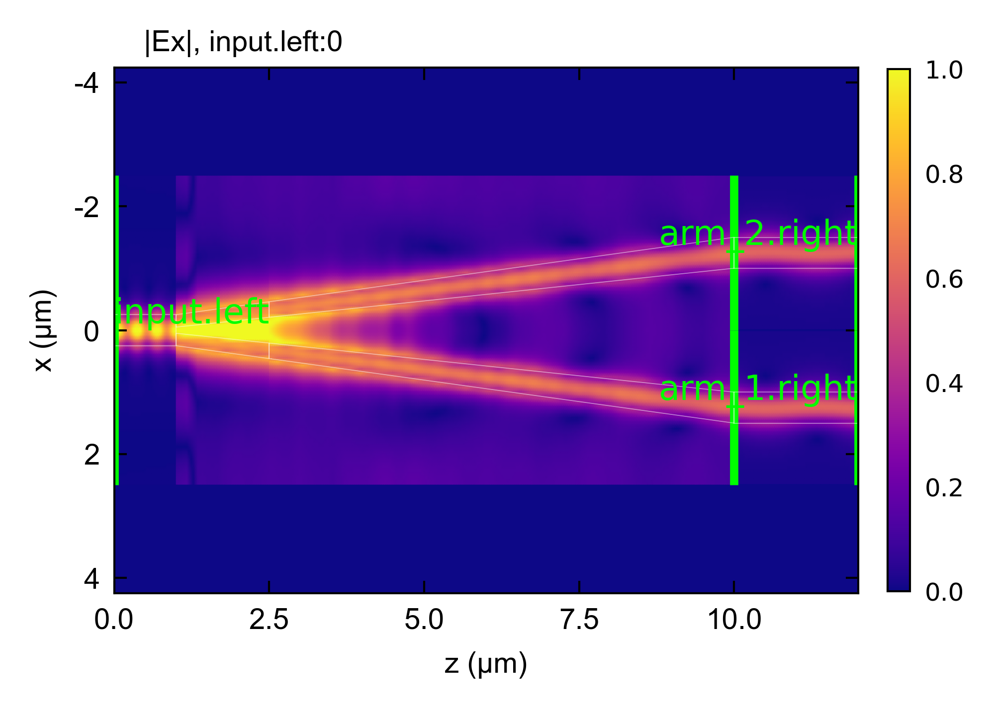
Layout. plot(view='layout') draws every section where its connections place it on the chip, with bends turning and the sections after a turn turned with them. It shows what the circuit will look like as a mask, and with the field components it shows the field of the solved circuit on that layout. check_layout reports the same placement as data (overlaps, sections that cross themselves, how far a loop is from closing). A layout plot of declared sections works before EME.
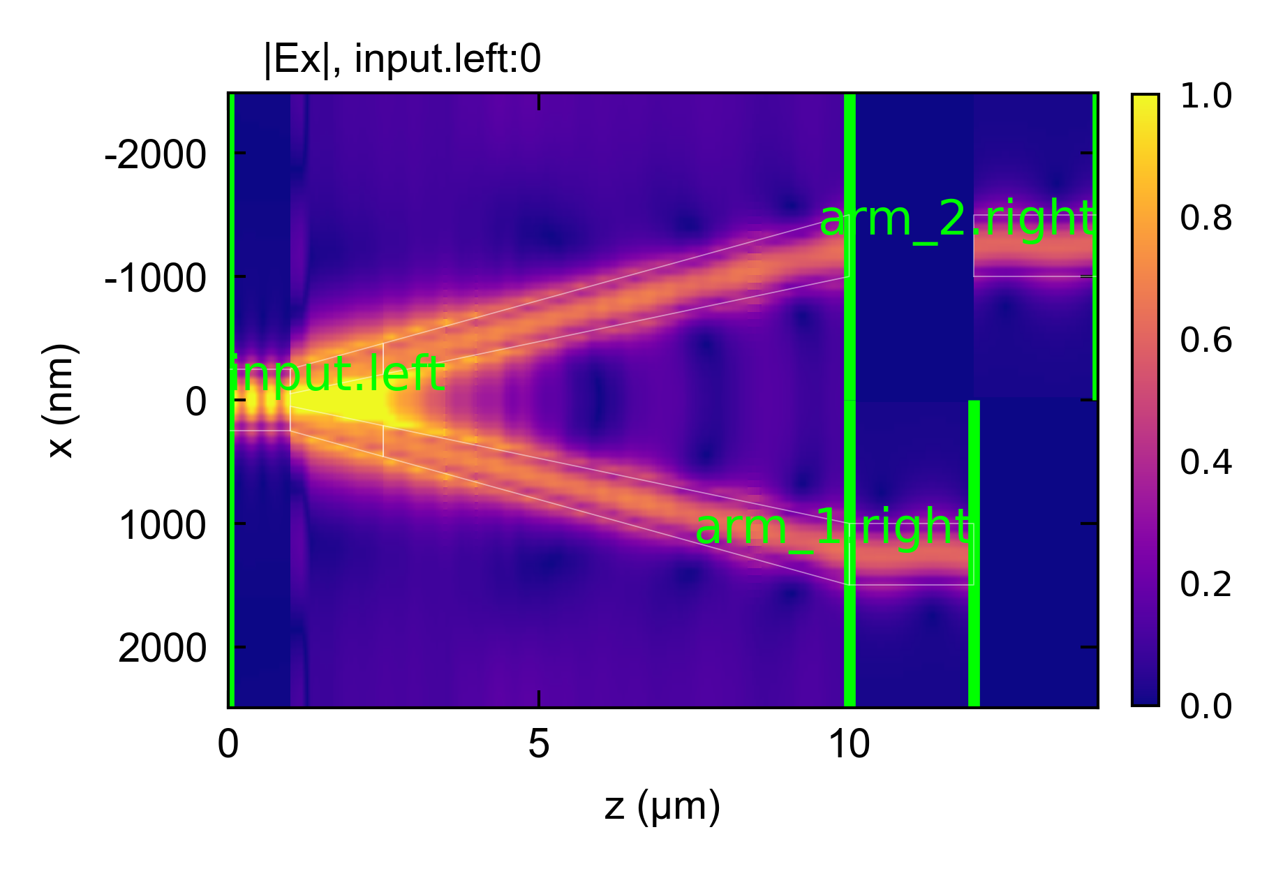
Simulation. plot(view='simulation') draws the circuit unrolled along its length, as the solver sees it: one axis along the light path, with no turns. It is the view for reading the field, the index and the slicing of a long circuit without the geometry of the chip getting in the way.
The schematic can also be shown as a panel of the plot window. Choose schematic in the Slice menu next to x-y, z-x and z-y. It saves through file_name like the others.
Walking the circuit section by section
Choose one section and every view zooms to it. From a script, pass its name:
em.plot(view='layout', component='Ex', plot_function='abs', section='split')
em.plot(plane='schematic', section='split', port='input.left')
In the plot window, use the Section menu. The layout view frames the section’s outline, the simulation view frames its span along the light path, and the schematic frames its block and its direct neighbors and outlines the selected block. Using the same name in the three views frames the same section in each, and switching view keeps the section. An unknown name raises an error that lists the sections.
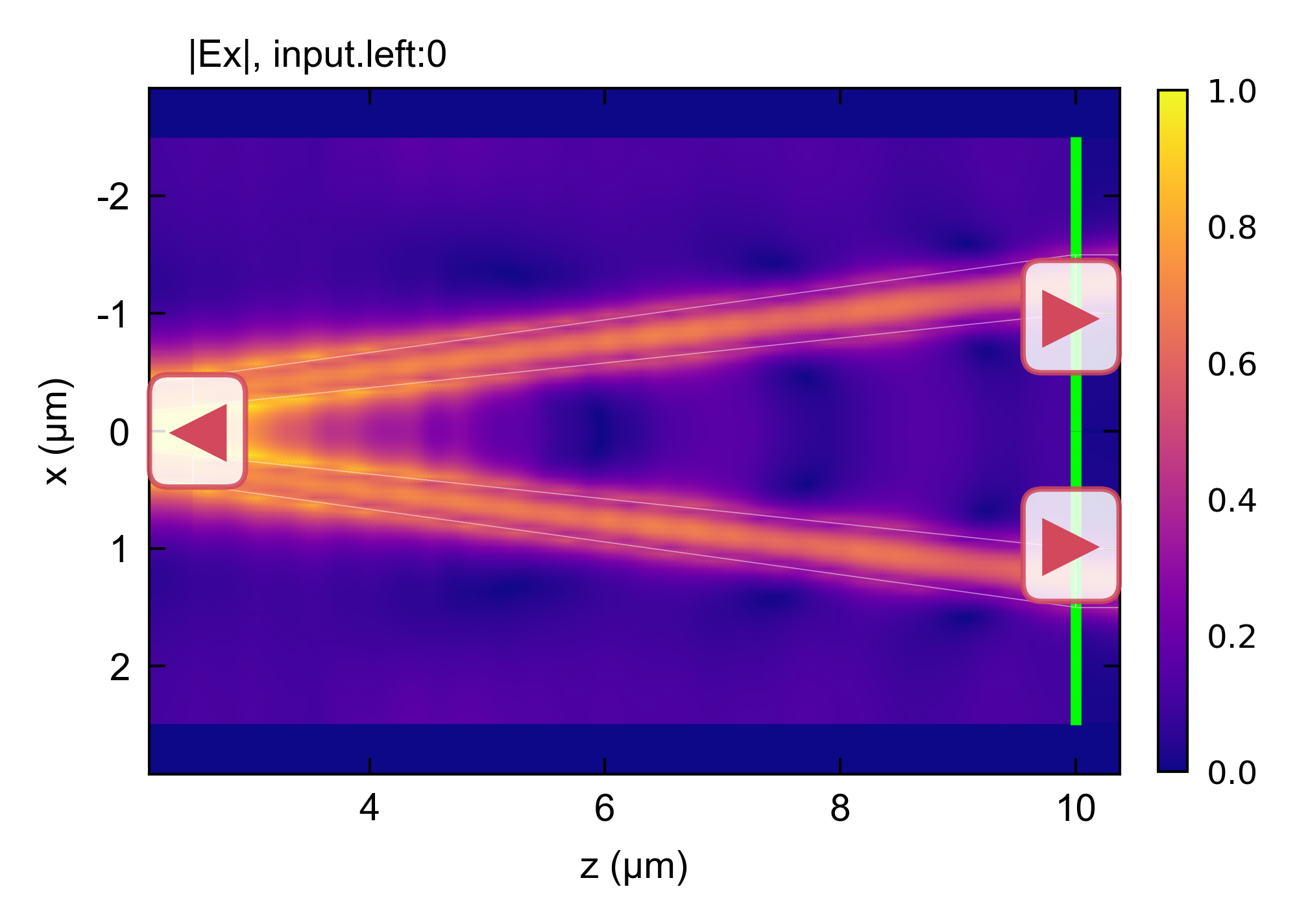
Arrows at the edges of the panel lead to the neighbors of the selected section, taken from the circuit’s connections. There is one arrow for each neighbor. Click an arrow to move to that section. Hovering over an arrow puts go to <section> in the status bar. The keyboard does the same:
Left and right arrows move along the light path, and a branch takes its lower arm first.
Up and down move between the arms of a branch, so the two outputs of the splitter reach each other without going back to the splitter.
Escape shows the whole circuit again.
In the schematic, clicking a block selects it.
On the Y-branch, starting at input and following the right arrow reaches tip, then split, and from split the right arrow leads to arm_2 (the lower arm) and the up arrow then to arm_1. Following the arrows from the input reaches every section of any circuit, a ring included.
The x-y panel shows one cross-section, so it is not zoomed to a section and has no arrows. The standalone view='schematic' call takes only port, file_name and file_type. Use plane='schematic' for a zoomed schematic.
Angled facets
A section that ends in a tilted facet shows the facet as a line at its angle on the layout, z-x and z-y panels. On the layout the line is placed from the pose of the section behind it, so it turns with a bend and keeps its angle to the end face of the section.
Reproducing the figures
The figures are made headless by emodeguide/Figures/circuit_views/make_figures.py, which declares a scaled-down version of the example circuit (a coarse grid and a few modes, so the field is a sketch of the real Y-branch rather than its result) and saves each view.